- Language
cat6 patch leads pass fluke test
Cat6 Patch Leads Fluke Test Compliance Guide
I. What is Cat6 Patch Leads Fluke Testing?
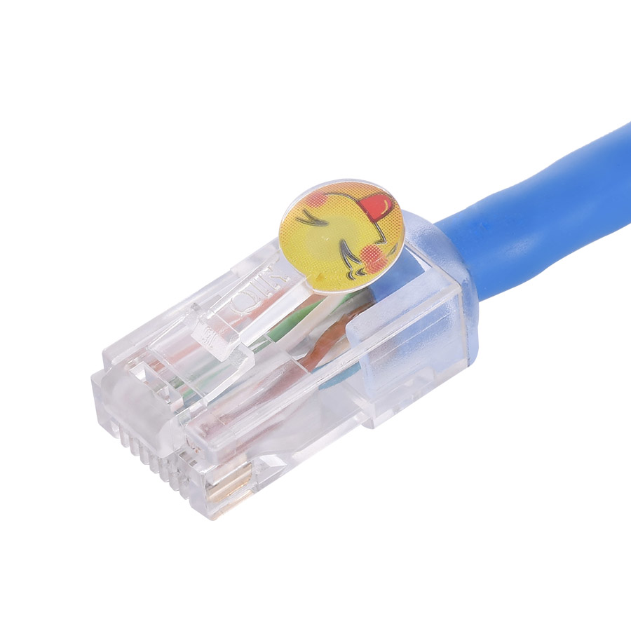
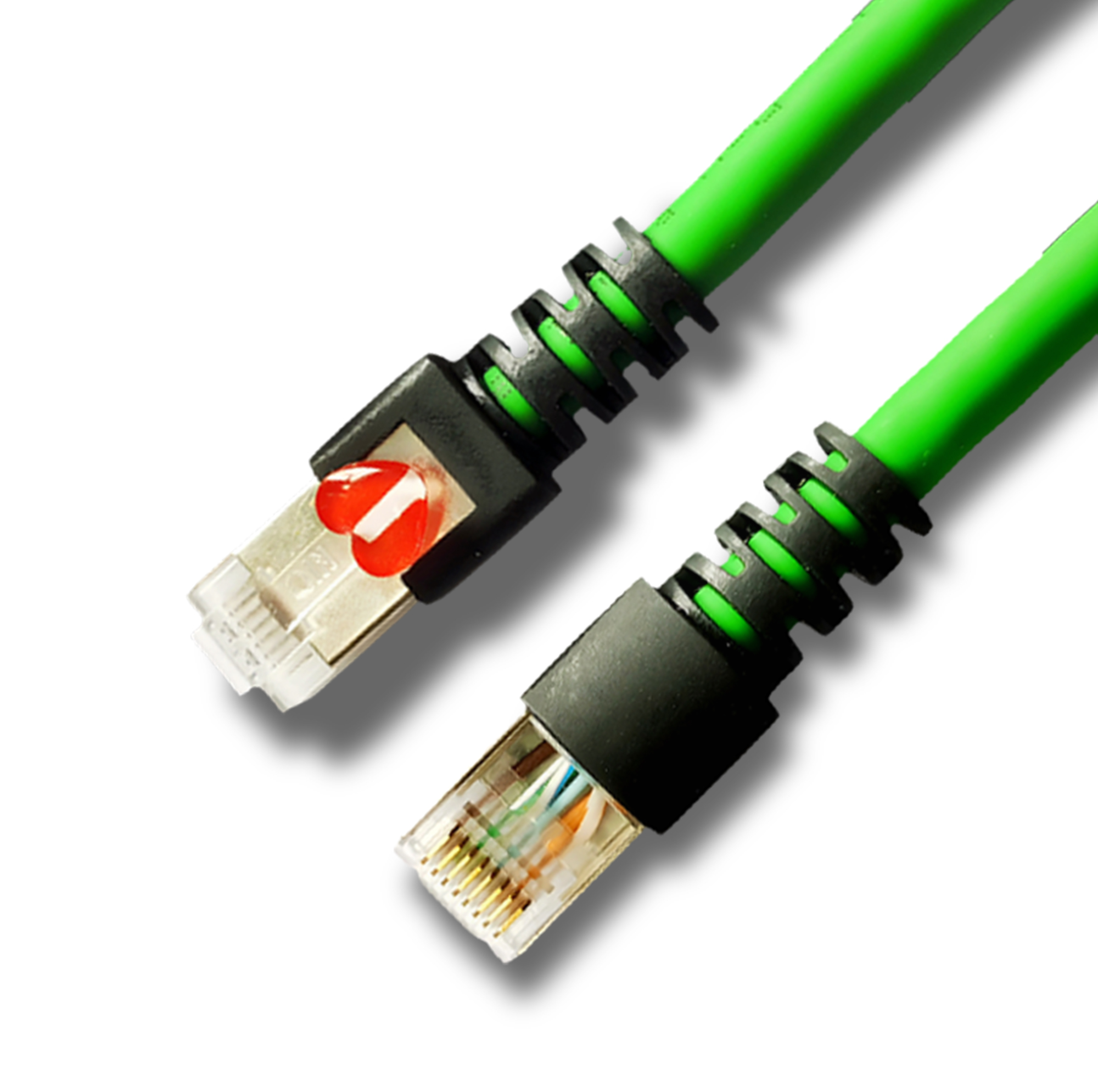
Cat6 patch lead Fluke testing is an authoritative testing method that uses Fluke professional network testers (such as the DSX-5000/DSX-1000) to verify the transmission performance of Cat6 (Category 6) patch leads according to internationally recognized standards. As a core connector for high-speed network transmission, Cat6 patch leads feature 250MHz bandwidth, support for 10Gbps transmission, precise pair twist pitch, and stable impedance matching. Fluke testing quantifies key performance indicators to ensure that patch leads meet the stringent requirements of "no excessive signal attenuation, no crosstalk interference, and no impedance mismatch." Its core features are **"standard compliance + performance quantification + authoritative certification" triple guarantee**, making it suitable for scenarios with extremely high transmission quality requirements, such as data centers, enterprise networks, and industrial Ethernet.
Compared to ordinary multimeter continuity testing, the core difference of Fluke's testing lies in its coverage of 12 key parameters across the entire frequency band (1-250MHz), rather than simply verifying "continuity." Compared to other brands of testing instruments, Fluke test reports possess industry-recognized authority and are the core basis for jumper product quality compliance and project acceptance.
II. Core Testing Principles The core of Fluke testing is "full-band performance scanning and standard threshold comparison." By transmitting test signals at specific frequencies, the signal transmission characteristics of the jumpers are analyzed to determine whether they comply with TIA/EIA-568-C.2 or ISO/IEC 11801 standards. The key logic is as follows:
Signal Transmission and Reception: The test instrument main unit transmits a sine wave signal in the 1-250MHz band, which is transmitted to a remote receiver via a Cat6 jumper. Data such as attenuation, reflection, and crosstalk during signal transmission are recorded.
Parameter Quantification and Analysis: The received signal is compared with the transmitted signal to calculate the measured values of 12 core parameters, including insertion loss, crosstalk, and return loss.
Standard Threshold Determination: The measured values are compared with preset Cat6 standard thresholds (such as TIA-568-C.2). If all parameters meet the requirements, the test is deemed "Pass"; if any parameter exceeds the limit, the test is deemed "Fail". "Fail"; Report Generation and Archiving: Automatically generates authoritative reports containing test standards, parameter details, measured curves, and equipment calibration information, supporting PDF export and project acceptance filing.
The entire process focuses on "signal transmission integrity," using sophisticated RF technology and a standard database to accurately identify patch cord manufacturing defects (such as poor RJ45 crimping, damaged wire pair twist) and performance shortcomings.
III. Core Test Parameters and Acceptable Thresholds (Based on TIA/EIA-568-C.2)
Insertion Loss (Attenuation, IL): Acceptable threshold is ≤7.5dB (250MHz, 10m jumper). Its core function is to measure energy loss during signal transmission and prevent weak signals received at distant ends.
Near-End Crosstalk (NEXT): Acceptable threshold is ≥-35.3dB (250MHz, 10m jumper). Its core function is to suppress signal interference between adjacent wire pairs at the same end, preventing data corruption.
Far-End Crosstalk (FEXT): Acceptable threshold is ≥-45.3dB (250MHz, 10m jumper). Its core function is to suppress signal interference between adjacent wire pairs at distant ends, ensuring stability over long distances.
Equivalent Far-End Crosstalk (ELFEXT): Acceptable threshold is ≥-38.6dB (250MHz, 10m jumper). The core function of the jumper cable is to comprehensively assess the combined effect of far-end crosstalk and insertion loss.
Return Loss (RL): The acceptable threshold is ≥10.0dB (full band, 10m jumper cable). Its core function is to reduce signal reflection and avoid superposition interference between reflected and original signals.
Near-End Crosstalk Power Sum (PSNEXT): The acceptable threshold is ≥-32.3dB (250MHz, 10m jumper cable). Its core function is to ensure the overall crosstalk suppression capability when multiple lines are transmitting simultaneously.
Equivalent Far-End Crosstalk Power Sum (PSELFEXT): The acceptable threshold is ≥-35.6dB (250MHz, 10m jumper cable). Its core function is to ensure the overall far-end crosstalk suppression capability when multiple lines are transmitting simultaneously.
Average Crosstalk Ratio (ACR-F): The acceptable threshold is ≥11.3dB (250MHz, 10m jumper cable). The core function of a patch cord is to ensure that the ratio of signal strength to crosstalk interference meets the standard, guaranteeing the dominance of the effective signal.
* Power Attenuation Crosstalk Ratio (PSACR-F): The acceptable threshold is ≥8.3dB (250MHz, 10m patch cord). Its core function is to ensure the effective signal dominance ratio in multi-pair transmission.
* Cable Length: The acceptable threshold is ≤10m (single patch cord segment). Its core function is to verify the compliance of patch cord length and avoid excessive attenuation due to excessive length.
* Propagation Delay: The acceptable threshold is ≤54.8ns (10m patch cord). Its core function is to control signal transmission delay and ensure real-time applications (such as video conferencing).
* Delay Skew: The acceptable threshold is ≤5.0ns (10m patch cord). Its core function is to control the transmission delay difference between four pairs and avoid data synchronization errors.
IV. Fluke Test Procedure (Taking DSX-5000 as an example)
1. Pre-test Preparation
Patch Cord Pre-treatment:
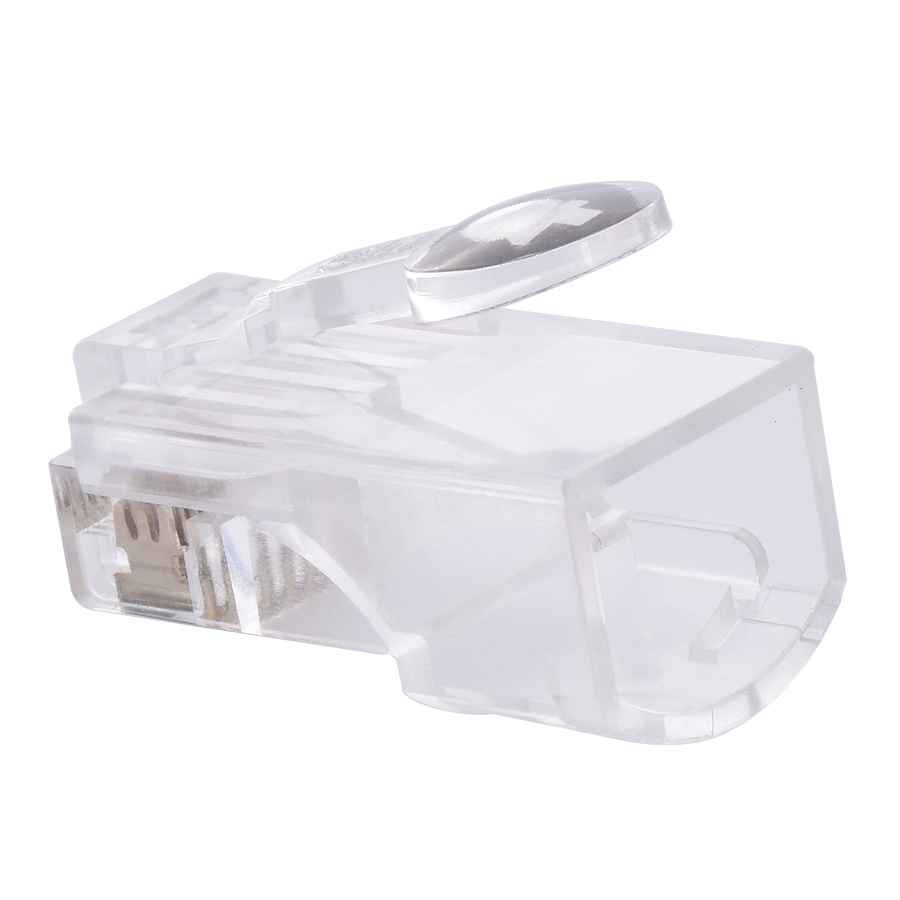
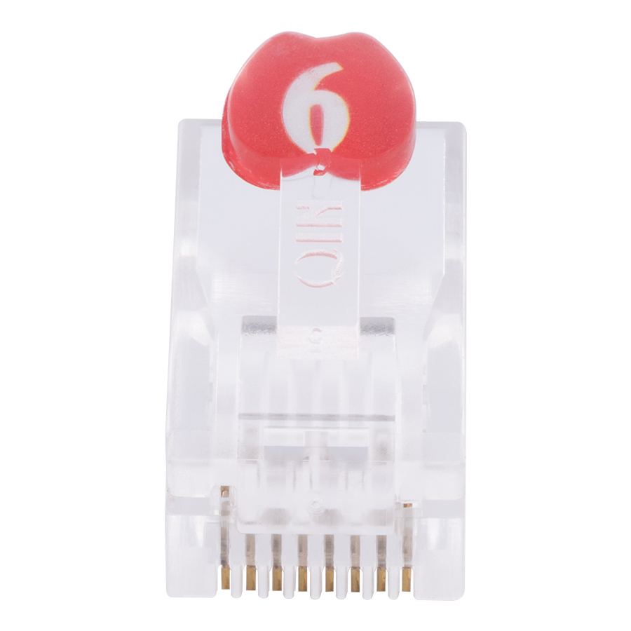
* Visual Inspection: Confirm that the patch cord is undamaged, the RJ45 connector clips are intact, the sheath is not cracked, and the markings are clear (Cat6/UTP/STP);
* Cleaning: Wipe the metal contacts of the RJ45 connector with anhydrous alcohol to remove oxide layer and stains (oxidation will increase contact resistance and affect test results);
* Specification Confirmation: Confirm that the patch cord length is ≤10m, the conductor wire diameter is 23-24AWG, and the wiring standard conforms to T568A/T568B (consistent at both ends). Equipment Calibration and Setup: Connect the Fluke calibration module (e.g., DSX-CAL) and perform "Automatic Calibration." The recommended calibration cycle is once every 12 months.
Select the test standard: TIA/EIA-568-C.2 (North America) or ISO/IEC 11801:2017 (International). Set the test mode to "Patch Cord" (for patch cords only).
Clean the test ports: Use a dedicated cleaning stick to wipe the RJ45 ports on both the main unit and the remote end to remove dust and contact oxide layers.
2. Test Connection and Execution
Following the tester's instructions, insert the RJ45 connectors at both ends of the jumper cable into the RJ45 test ports of the Main and Remote terminals respectively, ensuring the clips are fully engaged.
Select the test type: "Full Test" (full parameter test, recommended for production/acceptance scenarios) or "Quick Test" (suitable for on-site spot checks).
Start the test: The tester automatically scans the 1-250MHz frequency band, testing each of the 12 parameters. The test duration is approximately 30-60 seconds per jumper. Avoid touching the jumper cable or test port during the test.
3. Result Determination and Report Generation
Pass/Fail Judgment: If all measured values are within the acceptable threshold, a green "Pass" indicator will appear on the screen, and a test report with Fluke certification will be generated.
Failure Handling: If a red "Fail" indicator appears, check the specific parameters that exceeded the standard (e.g., "NEXT-35.0dB < -35.3dB"). After troubleshooting and rectification according to the "Common Problem Solutions," retest.
Report Export: Export the report as a PDF using LinkWare software. The report includes the test equipment serial number, calibration status, jumper model, and a comparison of all measured values with standard values, which can be used as acceptance documentation.
V. Common Test Failure Causes and Solutions
* **Return Loss (RL) Exceeds Standard:** Typical causes include poor crimping of the RJ45 connector, conductor oxidation, and impedance mismatch. Solutions include re-crimping the RJ45 connector (ensuring all 8 pins are connected and crimping force is even), replacing with a high-quality Cat6 certified RJ45 connector, and avoiding the use of copper-clad aluminum conductor jumpers.
* **Near-End Crosstalk (NEXT) Exceeds Standard:** Typical causes include damaged pair twist pitch, incorrect wiring sequence, and poor RJ45 connector quality. Solutions include strictly following the T568A/B standard for wiring, avoiding excessive stretching of the cable during crimping (which damages the twist pitch), using Cat6 jumpers with precise twist pitch, and replacing with brand-name RJ45 connectors.
* **Insertion Loss (IL) Exceeds Standard:** Typical causes include conductor breakage/poor contact, cable aging, and loose RJ45 connector. Solutions include checking the jumper's continuity, replacing broken cables, re-inserting the RJ45 connector to ensure a tight snap-fit, and avoiding the use of jumpers exceeding 10m in length. The jumper cable (single segment); Delay deviation exceeding the standard: Typical causes include inconsistent wire pair lengths and poor shielding grounding (STP); the solution is to use jumpers with a wire pair length deviation ≤3cm. For STP jumpers, ensure a reliable connection between the shielding layer and the RJ45 connector shielding shell to avoid shielding damage; No response during testing: Typical causes include port contamination, uncalibrated equipment, and incorrect jumper type selection; the solution is to clean the test port contacts, re-perform the calibration procedure, and confirm that the test mode is "Patch Cord" instead of "Permanent Link".
VI. Core Testing Equipment and Tools
Main Testing Equipment: Fluke DSX-5000 (supports Cat6/Cat6A/Cat7, high precision, suitable for laboratory/production testing), DSX-1000 (entry-level, suitable for engineering acceptance), DTX-1800 (classic model, high cost-performance ratio);
Auxiliary Tools: RJ45 crimping pliers (e.g., CommScope 110), wire strippers, RJ45 connector cleaning sticks, Fluke calibration module (DSX-CAL), LinkWare report management software, jumper cable storage box (to prevent excessive bending of jumper cables during testing);
Consumable Requirements: Cat6 certified RJ45 connectors (e.g., Panduit/AMP), pure copper conductor jumper cables (oxygen-free copper preferred, avoid copper-clad aluminum/copper-clad steel), Cat6 compliant sheathing materials (low smoke, halogen-free preferred). VII. Applicable Scenarios
Data center cabling project acceptance (e.g., patch cords connecting servers and switches);
Network equipment manufacturer patch cord factory testing (mass production quality control);
Enterprise-level network upgrades (e.g., 10Gbps upgrade of office networks);
Industrial Ethernet scenarios (e.g., PLC and sensor connections, with high anti-interference requirements);
Third-party testing agency product certification (obtaining authoritative quality endorsement);
Scenarios with high real-time transmission requirements, such as monitoring systems and video conferencing.
VIII. Limitations
* High Equipment Cost: The Fluke DSX-5000 series testers are expensive (approximately tens of thousands of yuan), making them unaffordable for small and medium-sized enterprises.
* High Operational Requirements: Requires professional personnel with skills in calibration, parameter interpretation, and troubleshooting; non-professionals are prone to misjudgment.
* Limited Testing Efficiency: Full-parameter testing of a single patch cord takes 30-60 seconds; batch testing requires automated testing fixtures to improve efficiency.
* Environmental Impact: Ambient temperature (18-25℃) and humidity (40%-60%) affect parameter accuracy; testing must be conducted under standard conditions.
* Verifies Transmission Performance Only: Does not test the mechanical strength (e.g., tensile life) or weather resistance (e.g., stability in high-temperature and high-humidity environments); requires additional testing.
Summary
The core of Cat6 patch cords passing Fluke testing is "standard and compliant process design + precise equipment testing": ensuring that the patch cord conforms to the Cat6 standard from conductor material and twist pitch design to RJ45 crimping, and then passing full-parameter scanning and authoritative verification by the Fluke tester, is essential to guarantee the stability of 10Gbps high-speed transmission. This test is a crucial step in network engineering quality control. Its authoritative report not only serves as a core endorsement of product quality but also as an important guarantee against subsequent network lag, packet loss, and substandard transmission rates. For enterprises and contractors prioritizing network reliability, Fluke testing and certification for Cat6 patch cords is an indispensable quality threshold and a core means of improving project delivery quality.
-
-
-
-
-
-
-
-
-
-
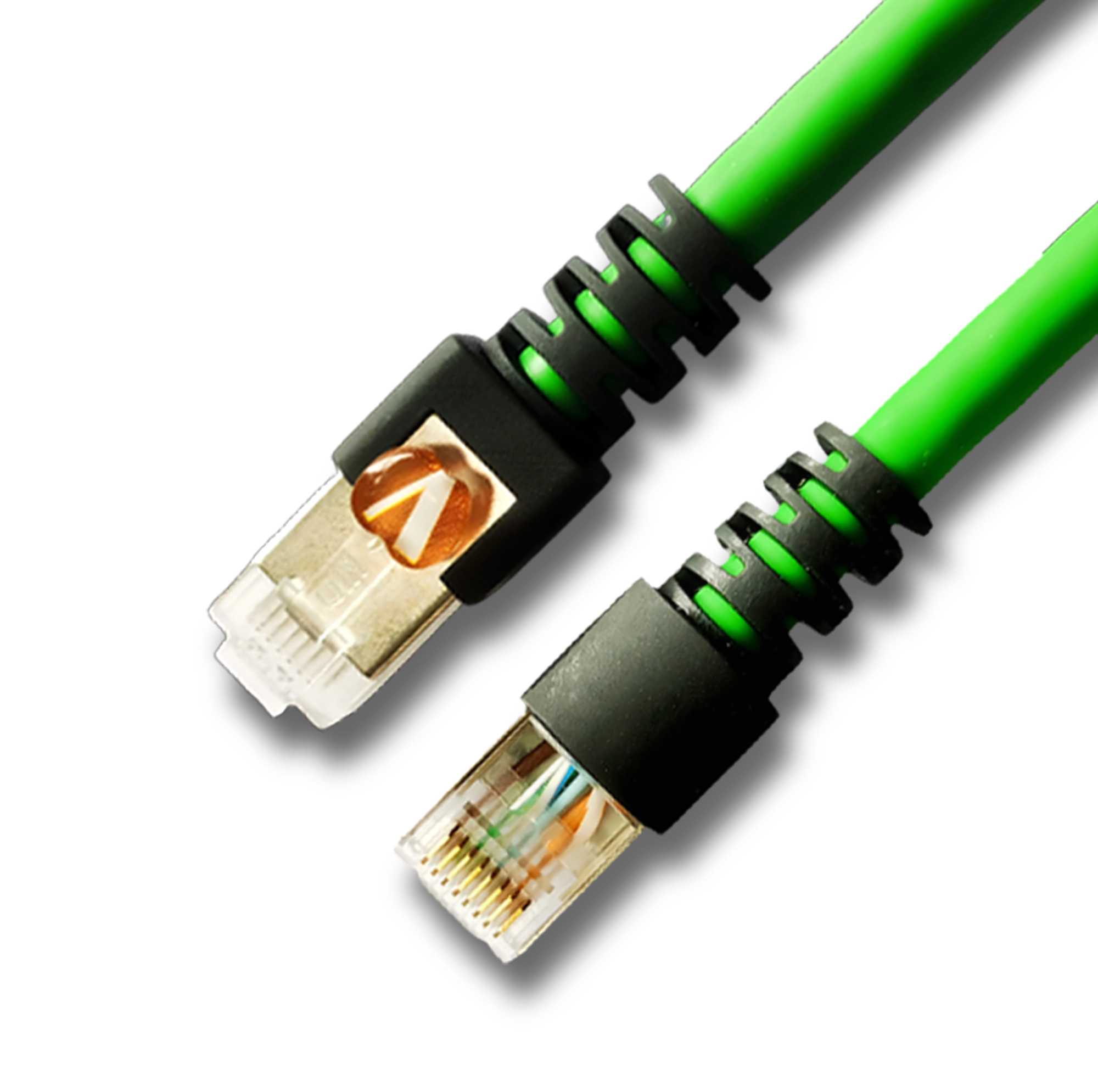
Network Patch Cord Cat8
Oct 23, 202592
-
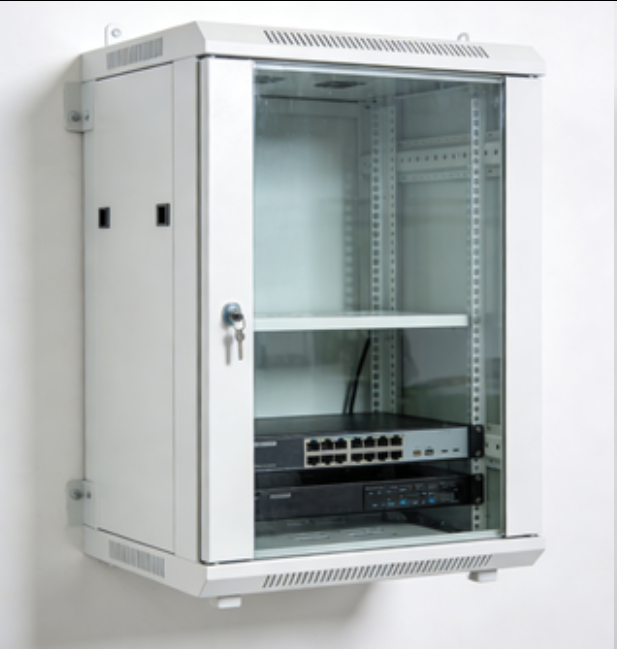
Network Rack Wall Mount with Glass Door
Jan 07, 202679
-
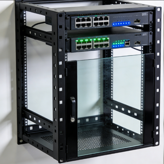
Network Rack Wall Mount 9U
Jan 06, 202675
-

Network Cable Management Tray
Oct 30, 202573
-

Network Cable Management Under Desk
Dec 25, 202572