- Language
cat6a patch cord pass fluke test
Cat6A Patch Cord Fluke Test Compliance Guide
1. What is Cat6A Patch Cord Fluke Test?
Cat6A Patch Cord Fluke Test is an authoritative testing method that uses professional Fluke network testers (such as DSX-5000/DSX-1000) to quantitatively verify the high-speed transmission performance of Cat6A (Augmented Category 6) patch cords in accordance with international universal standards.
As a core connector for next-generation high-speed networks, Cat6A patch cords feature 500MHz bandwidth (twice that of Cat6), support for 10Gbps transmission rate (extending to 100m), ultra-precise twist pitch design, more stable 100Ω impedance matching, and dual shielded/unshielded versions for high-interference environments. The Fluke test accurately detects 12 key transmission indicators to ensure the patch cord meets the stringent requirements of "controllable high-frequency signal attenuation, extreme crosstalk suppression between pairs, no impedance mismatch, and qualified anti-interference capability". Its core value lies in the triple guarantee of "high-speed transmission endorsement + high-interference environment adaptation + authoritative engineering acceptance recognition", and it is widely used in data centers, 10Gbps enterprise networks, industrial Ethernet, high-density cabling and other scenarios with extremely high requirements for transmission rate and stability.
Compared with Cat6 patch cord testing, the core differences are: test frequency band extended to 500MHz (Cat6 is 250MHz), stricter parameter thresholds (e.g., crosstalk suppression requirements increased by over 30%), and emphasis on verifying shielding performance (for STP/SFTP types). Compared with ordinary testers, Fluke test can accurately capture performance shortcomings in the high-frequency band (250-500MHz), and its report has the sole validity for 10Gbps network engineering acceptance.
2. Core Testing Principle
The core logic of Fluke test is "500MHz full-band scanning + Cat6A-specific threshold comparison". By simulating actual 10Gbps network transmission scenarios, it quantitatively evaluates the integrity of high-frequency signal transmission of patch cords. The specific process is as follows:
Signal Transmission and Reception: The tester's main unit transmits continuous sine wave test signals in the 1-500MHz frequency band (covering the full bandwidth of Cat6A) to the Cat6A patch cord. The remote receiver synchronously collects the transmitted signals and records data such as attenuation, reflection, crosstalk, and external interference in the high-frequency band.
Parameter Quantitative Calculation: By comparing the amplitude and phase differences between the transmitted and received signals, the measured values of 12 core performance indicators such as insertion loss, crosstalk, and return loss are accurately calculated, with emphasis on enhancing data accuracy in the high-frequency band (250-500MHz).
Standard Compliance Judgment: The measured values are compared with the Cat6A-level thresholds specified in TIA/EIA-568-C.2-1 (North American standard) or ISO/IEC 11801:2017 Class EA (international standard). If all indicators meet the requirements, it is judged as "Pass"; if any indicator exceeds the limit, it is judged as "Fail".
Authoritative Report Generation: Automatically generate a PDF report including test standards, patch cord specifications (including shielding type), equipment calibration information, 500MHz full-band parameter curves, and comparison between measured values and thresholds, supporting filing and quality traceability for 10Gbps network engineering acceptance.
The entire testing process focuses on "high-frequency signal transmission integrity + anti-interference capability". Through precision radio frequency technology and Cat6A-specific standard database, it accurately identifies high-frequency process defects of patch cords (such as uneven twist pitch and poor shielding layer grounding), avoiding problems such as lag, packet loss, and rate degradation during 10Gbps network operation.
3. Core Test Parameters and Qualification Thresholds (Based on TIA/EIA-568-C.2-1 Standard, 10m Patch Cord)
Insertion Loss (IL): ≤12.0dB (500MHz) – Measures the energy loss of 500MHz high-frequency signal transmission to ensure the signal strength at the far end meets the requirements under 10Gbps rate.
Near-End Crosstalk (NEXT): ≥-30.1dB (500MHz) – Extremely suppresses signal interference between adjacent pairs in the high-frequency band to prevent data confusion in 10Gbps transmission.
Far-End Crosstalk (FEXT): ≥-40.1dB (500MHz) – Suppresses far-end high-frequency crosstalk to ensure stable 100m long-distance 10Gbps transmission.
Equal-Level Far-End Crosstalk (ELFEXT): ≥-33.4dB (500MHz) – Comprehensively evaluates the combined impact of far-end crosstalk and insertion loss to ensure high-frequency effective signals dominate.
Return Loss (RL): ≥10.0dB (1-500MHz full band) – Reduces high-frequency signal reflection to avoid interference caused by superposition of reflected signals and original signals.
Power Sum NEXT (PSNEXT): ≥-27.1dB (500MHz) – Ensures the total crosstalk suppression capability when multiple pairs transmit 10Gbps signals simultaneously.
Power Sum ELFEXT (PSELFEXT): ≥-30.4dB (500MHz) – Ensures the total far-end crosstalk suppression capability when multiple pairs transmit 10Gbps signals simultaneously.
Attenuation-to-Crosstalk Ratio (ACR-F): ≥6.4dB (500MHz) – Measures the ratio of high-frequency signal strength to crosstalk interference to ensure effective signals are distinguishable.
Power Sum ACR-F (PSACR-F): ≥3.4dB (500MHz) – Ensures the effective signal dominance ratio when multiple pairs transmit 10Gbps signals.
Cable Length: ≤10m (single patch cord) – Avoids excessive high-frequency signal attenuation due to overlength.
Propagation Delay: ≤548ns (100m channel, including patch cord) – Controls 10Gbps transmission delay to meet low-latency requirements of industrial control, cloud computing, etc.
Delay Skew: ≤50ns (100m channel) – Controls the transmission delay difference between four pairs to avoid 10Gbps data synchronization errors.
Alien Crosstalk (AX): ≥-35.0dB (500MHz, multi-patch cord parallel scenario) – Only applicable to UTP-type Cat6A, suppressing high-frequency interference between adjacent patch cords (not a mandatory requirement for Cat6).
4. Fluke Test Operation Procedure (Taking DSX-5000 as an Example)
4.1 Pre-Test Preparation
(1) Patch Cord Preprocessing (Emphasizing Cat6A Characteristics)
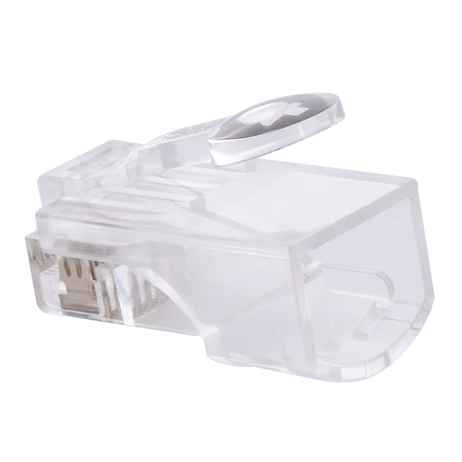
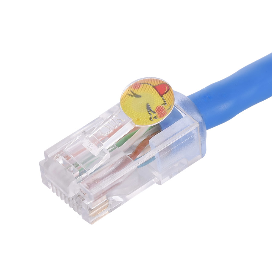
Visual Inspection: Confirm the patch cord jacket is intact, crystal head clips are undamaged, and markings are clear (marked with Cat6A/UTP/SFTP). For SFTP types, check that the shielding layer is intact and grounding terminals are in good condition.
Cleaning Treatment: Wipe the gold-plated contacts of the crystal head with anhydrous alcohol (Cat6A recommends ≥50μin gold plating) to remove oxide layers and stains, avoiding increased high-frequency contact resistance.
Specification Verification: Confirm the patch cord length is ≤10m, conductor gauge is 23-24AWG (oxygen-free copper material), wiring standard is consistent (both ends are T568A or T568B), and for SFTP types, verify that the shielding layer is reliably connected to the crystal head shield.
(2) Equipment Calibration and Settings (Key Differences)
Instrument Calibration: Connect the Fluke dedicated calibration module (DSX-CAL) and perform "500MHz full-band calibration". The calibration cycle is shortened to once every 6 months (higher precision requirements for high-frequency testing).
Standard Selection: In the tester, select "TIA/EIA-568-C.2-1 Cat6A" or "ISO/IEC 11801 Class EA", set the test mode to "Patch Cord", and enable "Alien Crosstalk" test (mandatory for UTP types).
Port Cleaning: Wipe the RJ45 ports of the tester's main unit and remote unit with a dedicated gold-plated contact cleaning rod to ensure no contact loss in high-frequency signal transmission.
4.2 Test Connection and Execution
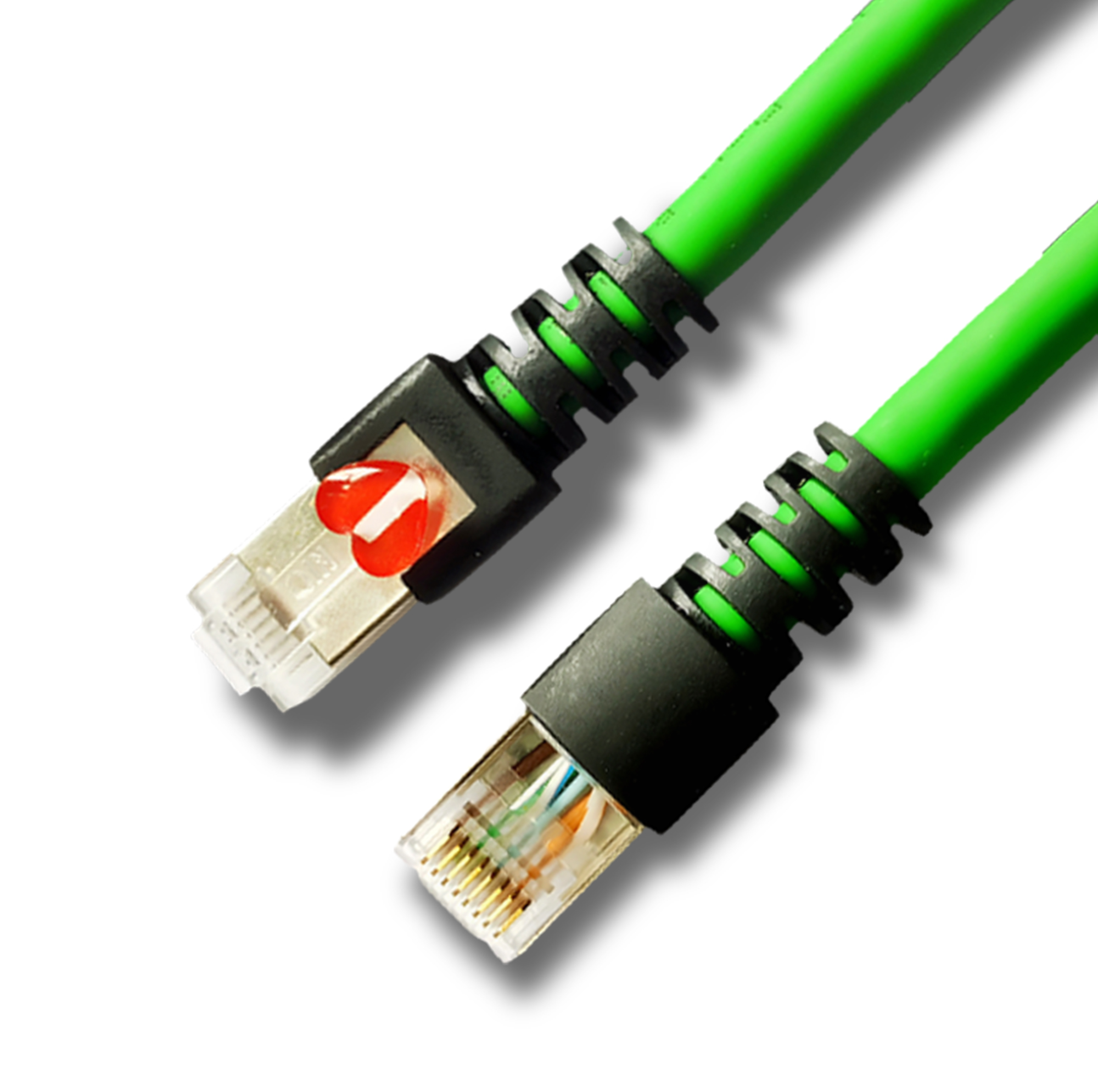
Physical Connection: Insert the RJ45 crystal heads at both ends of the patch cord into the RJ45 test ports of the tester's main unit and remote unit respectively, ensuring the clips are fully engaged. For SFTP types, confirm the tester ports are properly grounded.
Test Type Selection: For production testing or engineering acceptance scenarios, "Full Test (full parameters + alien crosstalk test)" must be selected. The test duration is approximately 60-90 seconds per cord (increased time due to high-frequency band scanning).
Start Testing: The tester automatically scans the 1-500MHz full band and sequentially detects 12+1 core parameters (including alien crosstalk). Avoid touching the patch cord or test ports during testing to prevent high-frequency signal interference.
4.3 Result Judgment and Report Generation
Qualification Judgment: If the measured values of all parameters (including the 500MHz band) are within the qualified thresholds, the tester displays a green "Pass" indicator and generates a test report with the "Cat6A Certified" certification mark.
Unqualified Handling: If a red "Fail" is displayed, focus on the over-limit parameters in the high-frequency band (250-500MHz) (e.g., "NEXT -29.8dB -30.1dB"), troubleshoot and rectify according to the "Common Test Failure Causes and Solutions" before retesting.
Report Export: Export the PDF report via LinkWare software. The report must include 500MHz band performance curves, alien crosstalk test results, and shielding performance verification (for SFTP types), which can be directly used as a certificate for 10Gbps network engineering acceptance.
5. Common Test Failure Causes and Solutions (Cat6A-Specific Optimization)
Near-End Crosstalk (NEXT) Over-Limit in High-Frequency Band (250-500MHz):
Typical Causes: Cat6A pairs have a denser twist pitch (usually ≤15mm), and excessive stretching during crimping damages the twist pitch; the internal pairs of the crystal head are excessively separated, leading to high-frequency interference leakage.
Solutions: Use Cat6A-specific crimping tools (to avoid excessive pair separation) and control the cable stretching amount to ≤5mm during crimping; replace with Cat6A-certified crystal heads (such as Panduit Mini-Com Cat6A series) to ensure the internal pair fixing structure meets high-frequency requirements.
Alien Crosstalk (AX) Over-Limit (UTP Type):
Typical Causes: Poor consistency of patch cord twist pitch; multiple patch cords placed too close in parallel during testing.
Solutions: Select Cat6A patch cords with twist pitch accuracy of ±0.5mm; place a single patch cord independently during testing (distance ≥10cm from other patch cords).
Insertion Loss (IL) Over-Limit in 500MHz Band:
Typical Causes: Substandard conductor material (not oxygen-free copper); crystal head gold plating thickness in; patch cord length close to the 10m upper limit.
Solutions: Replace with oxygen-free copper conductor patch cords; select Cat6A crystal heads with gold plating thickness ≥50μin; control the length of a single patch cord within 8m (reserving engineering redundancy).
SFTP Type Shielding Performance Non-Qualification:
Typical Causes: Loose connection between the shielding layer and the crystal head shield; damaged shielding layer or insufficient braiding density (%).
Solutions: Re-crimp the SFTP crystal head to ensure reliable contact between the shielding layer and the shield (conduction resistance ≤5Ω); select Cat6A SFTP patch cords with braiding density ≥95%.
Return Loss (RL) Fluctuation Over-Limit in Full Band:
Typical Causes: Cat6A has stricter impedance tolerance requirements (±3Ω), resulting in patch cord impedance mismatch; uneven crimping force of the crystal head leads to fluctuating contact resistance.
Solutions: Select Cat6A cables with impedance tolerance of ±2Ω; use torque-adjustable crimping tools (recommended torque 0.8-1.2N·m) to ensure uniform contact of 8 cores.
6. Core Test Equipment and Tool Configuration (Cat6A-Specific Adaptation)
6.1 Main Test Equipment (Must Support 500MHz)
Fluke DSX-5000: Preferred model, supporting Cat6A/Cat7/Cat8, with 500MHz band test accuracy of ±0.1dB, suitable for laboratory testing and mass production quality control.
Fluke DSX-1000: Cost-effective entry-level option, supporting full-parameter Cat6A testing, suitable for engineering acceptance and on-site sampling inspection.
Fluke DTX-1800: Requires upgrade to the latest firmware (v5.0+), supporting Cat6A 500MHz testing, suitable for small and medium-sized enterprises.
6.2 Auxiliary Tools (Cat6A-Specific)
Crimping Tools: Cat6A-specific crimping tools (such as CommScope Cat6A 110 type), dedicated shielding layer crimping tools (essential for SFTP types).
Auxiliary Tools: High-precision wire strippers (to avoid damaging pair twist pitch), RJ45 gold-plated contact cleaning rods, DSX-CAL 500MHz calibration module, LinkWare Pro advanced report software (supporting high-frequency curve analysis).
6.3 Consumable Requirements (Cat6A-Certified)
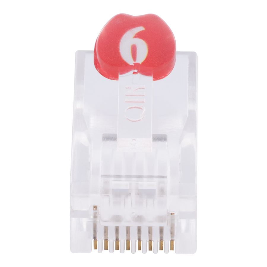
Crystal Heads: Must comply with Cat6A standards (supporting 500MHz), UTP types need to have pair isolation structures, and SFTP types need to have 360° shielding shells; gold plating thickness ≥50μin.
Patch Cord Conductors: Oxygen-free copper (purity ≥99.99%) with pair twist pitch accuracy of ±0.5mm.
Jacket Material: Low Smoke Zero Halogen (LSZH) or PVC complying with Cat6A standards; SFTP types need to be equipped with aluminum foil + braided double shielding (braiding density ≥95%).
7. Application Scenarios (Cat6A-Specific Upgrade)
10Gbps data center cabling (connections between servers and TOP-of-Rack switches, Storage Area Network (SAN) connections).
Enterprise-level 10Gbps network upgrades (office networks, R&D networks upgrading from 1Gbps to 10Gbps).
Industrial Ethernet scenarios (connections between PLCs and sensors, industrial switches, with high electromagnetic interference).
High-density cabling environments (data centers, server rooms with limited space, requiring high-performance and space-saving solutions).
Cloud computing and big data centers (high-speed data transmission between servers and storage devices, requiring low latency and high stability).
Financial industry core networks (stock trading systems, banking data centers, requiring ultra-reliable transmission).
Medical imaging systems (high-definition medical equipment data transmission, requiring no packet loss and low delay).
8. Limitations
High Equipment Cost: Fluke DSX-5000 series testers are expensive (approximately tens of thousands of US dollars), resulting in significant initial investment pressure for small and medium-sized enterprises.
High Operation Threshold: Requires professional personnel to master instrument calibration, parameter interpretation, and troubleshooting skills; non-professionals are prone to misjudgment.
Limited Test Efficiency: Full-parameter testing takes 60-90 seconds per patch cord; for mass testing, it is recommended to use automated test fixtures to improve efficiency.
Environmental Impact on Test Accuracy: The test environment temperature needs to be controlled at 18-25℃ and humidity at 40%-60%;
-
-
-
-
-
-
-
-
-
-
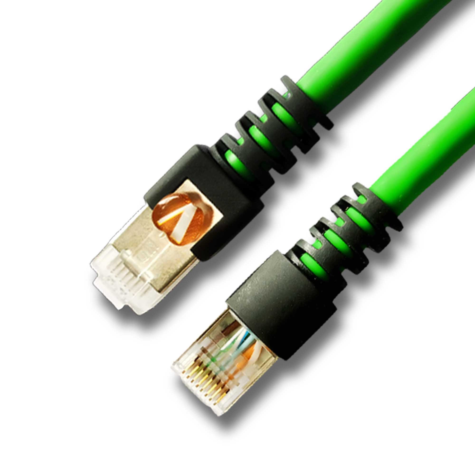
Network Patch Cord Cat8
Oct 23, 202592
-
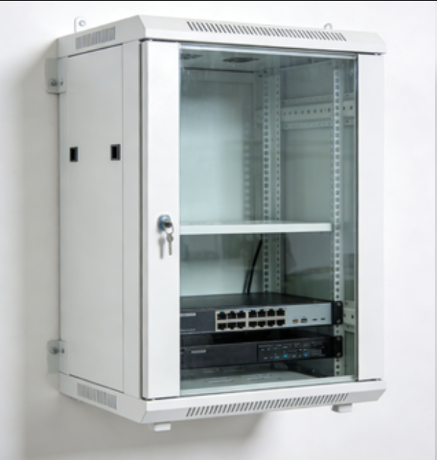
Network Rack Wall Mount with Glass Door
Jan 07, 202679
-
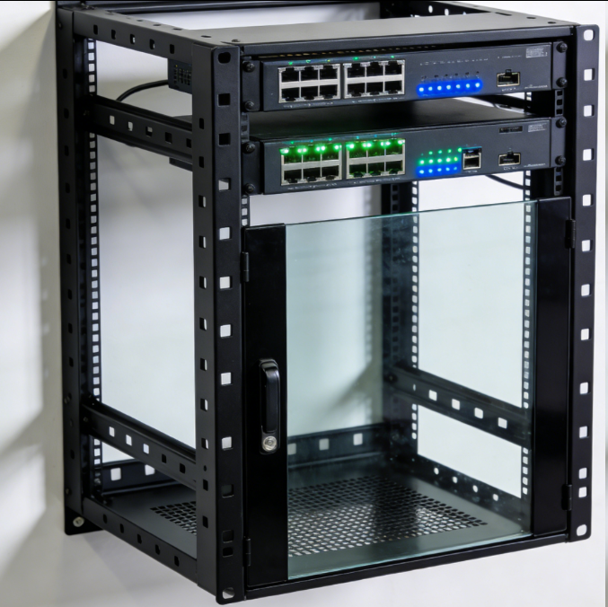
Network Rack Wall Mount 9U
Jan 06, 202675
-

Network Cable Management Tray
Oct 30, 202573
-

Network Cable Management Under Desk
Dec 25, 202572