- Language
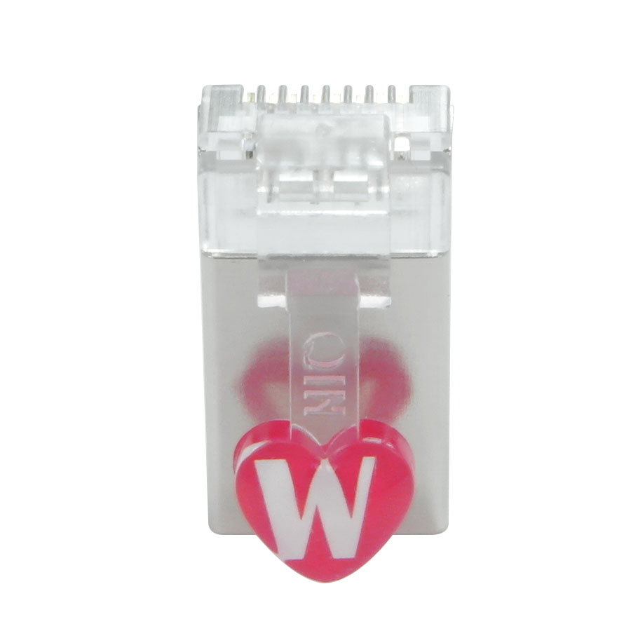
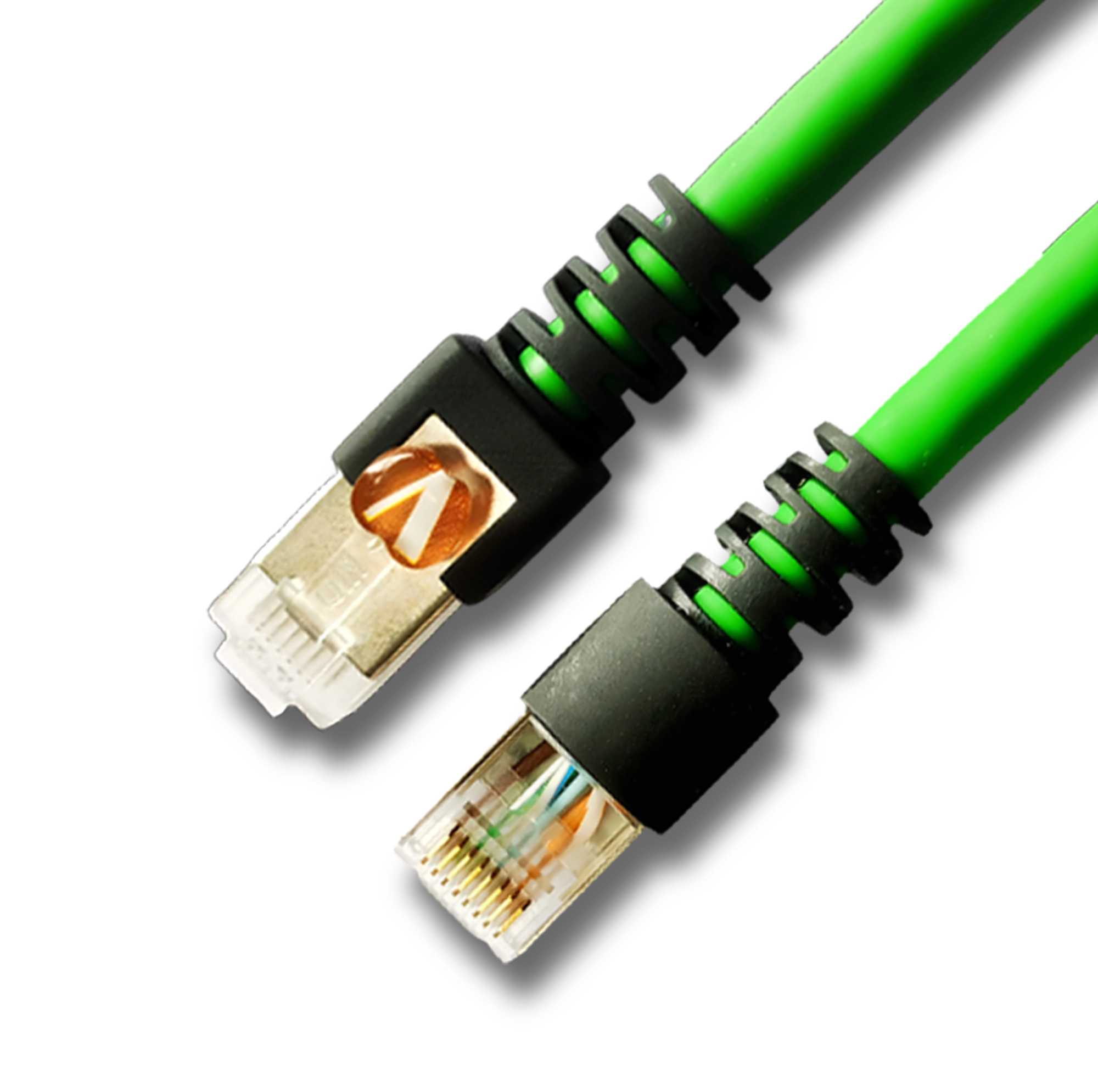
cat7 patch cable pass fluke test
Cat7 Patch Cable Fluke Test Compliance Guide
1. What is Cat7 Patch Cable Fluke Test?
Cat7 Patch Cable Fluke Test is an authoritative testing method that uses professional Fluke network testers (e.g., DSX-5000/DSX-8000) to quantitatively verify the ultra-high-speed transmission performance and shielding effectiveness of Cat7 (Category 7) patch cables in accordance with international standards.
As a premium high-speed network connector, Cat7 patch cables feature 600MHz bandwidth (1.2x that of Cat6A), support for 40Gbps transmission rate (up to 50m) and 10Gbps@100m, S/FTP (Screened/Foiled Twisted Pair) dual-shielded structure, ultra-precise twist pitch (≤12mm), and 100Ω impedance matching with ±2Ω tolerance. The Fluke test comprehensively detects 14 core indicators (including exclusive shielding performance parameters) to ensure the cable meets the stringent requirements of "ultra-high-frequency signal attenuation control, near-zero crosstalk, robust anti-interference capability, and stable shielding continuity". Its core value lies in the triple guarantee of "40Gbps transmission endorsement + extreme interference resistance + Class F engineering acceptance recognition", and it is widely used in 40Gbps data centers, enterprise backbone networks, industrial 4.0 high-speed Ethernet, AI computing clusters, and other scenarios with top-tier requirements for transmission speed and stability.
Compared with Cat6A patch cable testing, the core differences are:
Test frequency band extended to 600MHz (Cat6A is 500MHz);
Mandatory dual-shielding performance verification (Shield Attenuation, Shield Continuity);
Stricter crosstalk and alien crosstalk thresholds (suppression improved by 25%+ at 600MHz);
Compliance with ISO/IEC 11801:2017 Class F (Cat6A is Class EA);
Support for 40Gbps transmission scenario simulation.
Compared with ordinary testers, Fluke test accurately captures ultra-high-frequency (500-600MHz) performance defects and validates dual-shielding integrity, with reports recognized as the gold standard for 40Gbps network acceptance.
2. Core Testing Principle
The core logic of Fluke test is "600MHz full-band scanning + Cat7 Class F threshold comparison + dual-shielding performance verification". By simulating 40Gbps actual transmission scenarios, it quantitatively evaluates the integrity of ultra-high-frequency signal transmission and anti-interference capability of Cat7 patch cables. The specific process is as follows:
Signal Transmission and Reception: The tester's main unit transmits continuous sine wave test signals in the 1-600MHz frequency band (covering Cat7's full bandwidth) to the Cat7 patch cable. The remote receiver synchronously collects transmitted signals and records ultra-high-frequency attenuation, reflection, crosstalk, alien crosstalk, and shielding-related data.
Parameter Quantitative Calculation: By comparing the amplitude, phase, and impedance differences between transmitted and received signals, the measured values of 14 core indicators (including 600MHz-specific parameters and shielding performance) are accurately calculated, with enhanced precision in the 500-600MHz ultra-high-frequency band.
Standard Compliance Judgment: The measured values are compared with ISO/IEC 11801:2017 Class F thresholds (Cat7's core standard; TIA/EIA has no Cat7 classification). If all indicators (including shielding performance) meet requirements, it is judged as "Pass"; if any indicator exceeds limits, it is judged as "Fail".
Authoritative Report Generation: Automatically generate a PDF report including Class F standard compliance, patch cable specifications (S/FTP dual-shielded), equipment calibration records, 600MHz full-band parameter curves, shielding attenuation data, and measured vs. threshold comparisons—supporting 40Gbps network engineering acceptance and quality traceability.
The entire testing process focuses on "ultra-high-frequency signal integrity + dual-shielding effectiveness". Through precision RF technology and Cat7-specific databases, it accurately identifies defects such as uneven twist pitch, shield layer damage, and poor grounding—avoiding lag, packet loss, or rate degradation in 40Gbps networks.
3. Core Test Parameters and Qualification Thresholds (Based on ISO/IEC 11801:2017 Class F, 10m Patch Cable)
Insertion Loss (IL): ≤13.5dB (600MHz) – Controls energy loss of 600MHz ultra-high-frequency signals, ensuring stable 40Gbps transmission.
Near-End Crosstalk (NEXT): ≥-28.0dB (600MHz) – Suppresses ultra-high-frequency crosstalk between adjacent pairs to prevent data corruption.
Far-End Crosstalk (FEXT): ≥-38.0dB (600MHz) – Ensures long-distance (up to 50m) 40Gbps transmission stability by mitigating far-end crosstalk.
Equal-Level Far-End Crosstalk (ELFEXT): ≥-31.3dB (600MHz) – Comprehensively evaluates combined impacts of far-end crosstalk and insertion loss.
Return Loss (RL): ≥10.0dB (1-600MHz full band) – Reduces signal reflection to avoid interference from signal superposition.
Power Sum NEXT (PSNEXT): ≥-25.0dB (600MHz) – Guarantees total crosstalk suppression for multi-pair 40Gbps transmission.
Power Sum ELFEXT (PSELFEXT): ≥-28.3dB (600MHz) – Ensures total far-end crosstalk suppression for multi-pair 40Gbps transmission.
Attenuation-to-Crosstalk Ratio (ACR-F): ≥4.5dB (600MHz) – Maintains effective signal dominance over crosstalk in ultra-high-frequency bands.
Power Sum ACR-F (PSACR-F): ≥1.5dB (600MHz) – Ensures effective signal ratio for multi-pair 40Gbps transmission.
Cable Length: ≤10m (single patch cable) – Avoids excessive attenuation in ultra-high-frequency bands.
Propagation Delay: ≤548ns (100m channel) – Controls transmission latency for low-latency scenarios (e.g., AI computing, industrial control).
Delay Skew: ≤50ns (100m channel) – Minimizes transmission delay differences between four pairs to prevent synchronization errors.
Alien Crosstalk (AX): ≥-32.0dB (600MHz, multi-cable parallel) – Strictly suppresses ultra-high-frequency interference between adjacent cables (mandatory for Class F).
Shield Attenuation: ≥80dB (600MHz) – Verifies dual-shielding (aluminum foil + braid) effectiveness in blocking external electromagnetic interference (EMI).
4. Fluke Test Operation Procedure (Taking DSX-5000 as an Example)
4.1 Pre-Test Preparation
(1) Patch Cable Preprocessing (Cat7-Specific Focus)
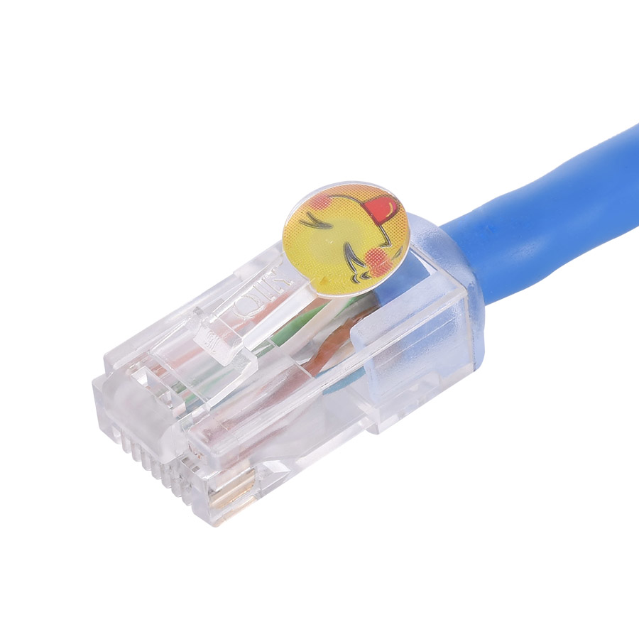
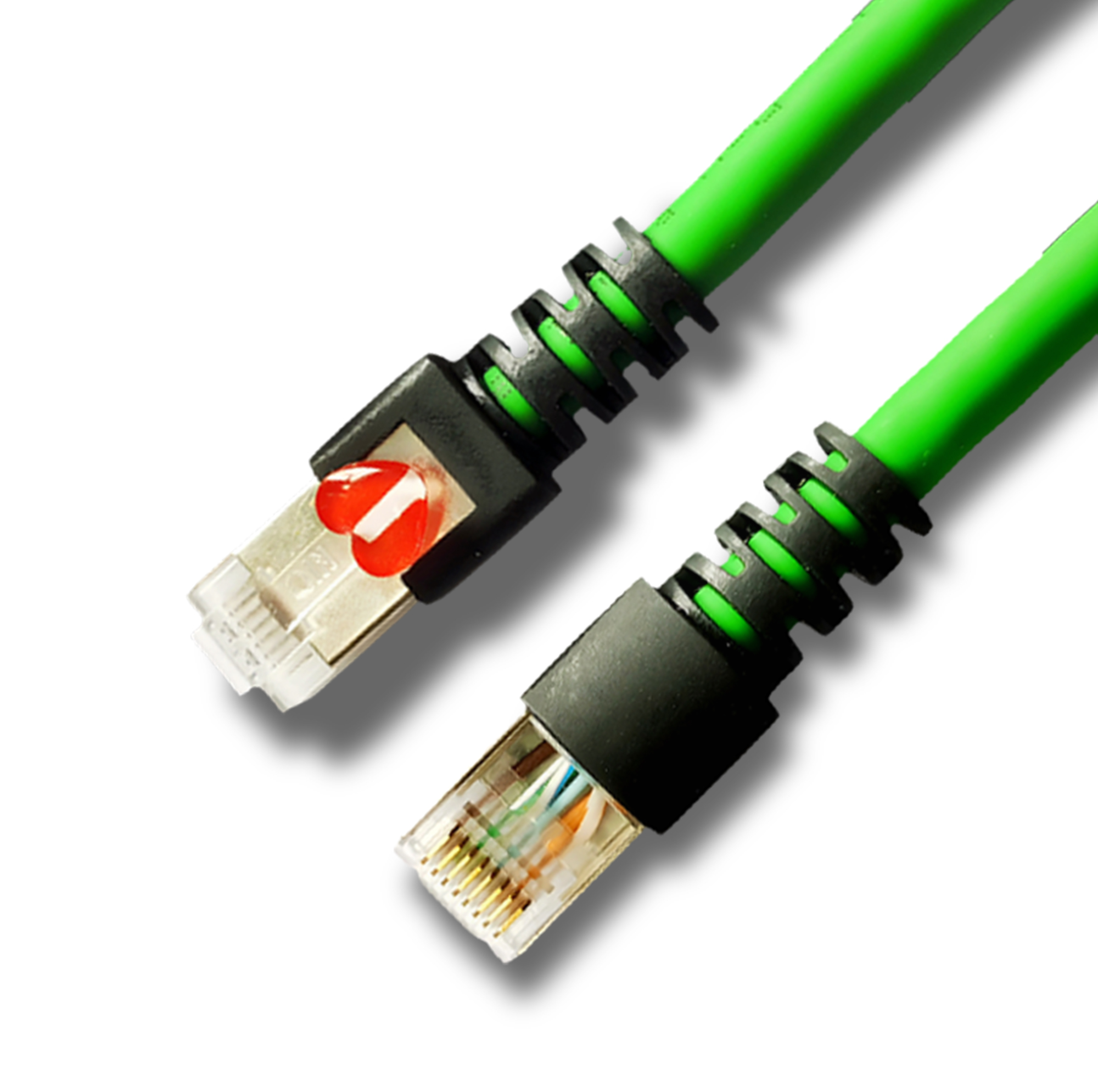
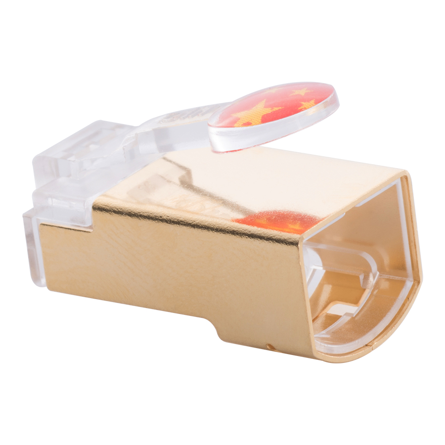
Visual Inspection: Confirm the S/FTP dual-shielded structure is intact (aluminum foil unbroken, braided layer ≥95% coverage), jacket undamaged, crystal head (GG45/RJ45 compatible) clips intact, and markings clear (Cat7/S/FTP/600MHz).
Cleaning Treatment: Wipe gold-plated contacts (≥50μin) of GG45/RJ45 connectors with anhydrous alcohol to remove oxides—critical for ultra-high-frequency contact reliability.
Specification Verification: Confirm length ≤10m, conductor gauge 23-24AWG (oxygen-free copper, purity ≥99.99%), consistent wiring standard (T568A/B), and dual-shield layer reliably connected to the connector's shield shell (conduction resistance ≤3Ω).
(2) Equipment Calibration and Settings (Key Updates)
Instrument Calibration: Connect Fluke DSX-CAL calibration module and perform "600MHz full-band calibration"—calibration cycle shortened to once every 3 months (ultra-high-frequency testing demands higher precision).
Standard Selection: In the tester, select "ISO/IEC 11801:2017 Class F", set test mode to "Patch Cable", and enable "Alien Crosstalk" and "Shield Attenuation" tests (mandatory for Cat7).
Port Preparation: Clean tester's GG45/RJ45 compatible ports with gold-plated contact cleaning rods to eliminate contact loss in 600MHz band.
4.2 Test Connection and Execution
Physical Connection: Insert Cat7 patch cable's GG45/RJ45 connectors into the tester's main and remote ports, ensuring full engagement. Confirm the tester's ground is connected (critical for shielding performance verification).
Test Type Selection: For production/acceptance, select "Full Test (14 parameters + shield attenuation + alien crosstalk)"—test duration ~90-120 seconds per cable (extended due to 600MHz scanning and shielding tests).
Start Testing: The tester automatically scans 1-600MHz, sequentially detecting all core parameters. Avoid touching the cable/ports during testing to prevent EMI interference.
4.3 Result Judgment and Report Generation
Qualification Judgment: If all parameters (including 600MHz band and shielding attenuation) meet thresholds, the tester displays a green "Pass" indicator and generates a "Cat7 Class F Certified" report.
Unqualified Handling: For red "Fail", prioritize ultra-high-frequency (500-600MHz) and shielding-related parameters (e.g., "Shield Attenuation 75dB 0dB"). Troubleshoot per Section 5 and retest.
Report Export: Export PDF via LinkWare Pro software—report must include 600MHz performance curves, shield attenuation data, alien crosstalk results, and Class F compliance marks for 40Gbps network acceptance.
5. Common Test Failure Causes and Solutions (Cat7-Specific Optimization)
Shield Attenuation 00MHz):
Typical Causes: Dual-shield layer (aluminum foil/braid) damaged; braided coverage %; shield layer poorly connected to connector shell; connector shield shell deformed.
Solutions: Replace patch cables with intact dual-shield layers (braided coverage ≥95%); re-crimp using Cat7-specific tools to ensure shield-conductor shell contact (resistance ≤3Ω); use connectors with 360° shield coverage.
NEXT Over-Limit in 500-600MHz Band:
Typical Causes: Cat7's ultra-dense twist pitch (≤12mm) damaged by excessive stretching during crimping; connector internal pair separation >3mm.
Solutions: Use Cat7-specific crimping tools to limit cable stretching ≤3mm; select connectors with integrated pair isolation structures (e.g., Panduit Cat7 GG45); ensure twist pitch consistency (±0.3mm).
Alien Crosstalk (AX) Over-Limit:
Typical Causes: Poor twist pitch uniformity; multi-cables placed <10cm apart during testing; external EMI interference.
Solutions: Select Cat7 cables with twist pitch accuracy ±0.3mm; test single cables independently (distance ≥15cm from others); perform testing in EMI-shielded environments.
Insertion Loss Over-Limit in 600MHz Band:
Typical Causes: Conductor purity 9% (non-oxygen-free copper); gold plating thickness cable length >10m.
Solutions: Use oxygen-free copper (99.99%+) conductors; select ≥50μin gold-plated connectors; limit single cable length ≤8m (reserve engineering redundancy).
Return Loss Fluctuation Over-Limit:
Typical Causes: Cat7's strict impedance tolerance (±2Ω) violated; uneven crimping force leading to contact resistance fluctuations; connector impedance mismatch.
Solutions: Use Cat7 cables with impedance tolerance ±1Ω; crimp with torque-adjustable tools (0.9-1.3N·m); select Class F-certified connectors (impedance 100Ω±1Ω).
6. Core Test Equipment and Tool Configuration (Cat7-Specific Adaptation)
6.1 Main Test Equipment (Must Support Class F)
Fluke DSX-5000: Preferred—supports Cat7/Cat8, 600MHz accuracy ±0.1dB, ideal for lab/mass production testing.
Fluke DSX-8000
-
-
-
-
-
-
-
-
-
-
Network Patch Cord Cat8
Oct 23, 202592
-
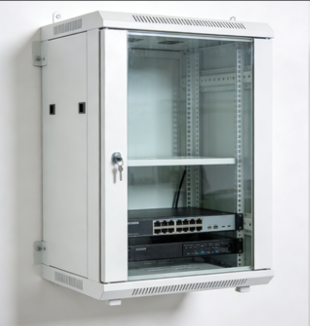
Network Rack Wall Mount with Glass Door
Jan 07, 202682
-

Network Cable Management Rack Shelf
Dec 17, 202582
-

Multi-Mode Fiber Loopback Patch Cord (SC-SC)
Dec 18, 202580
-
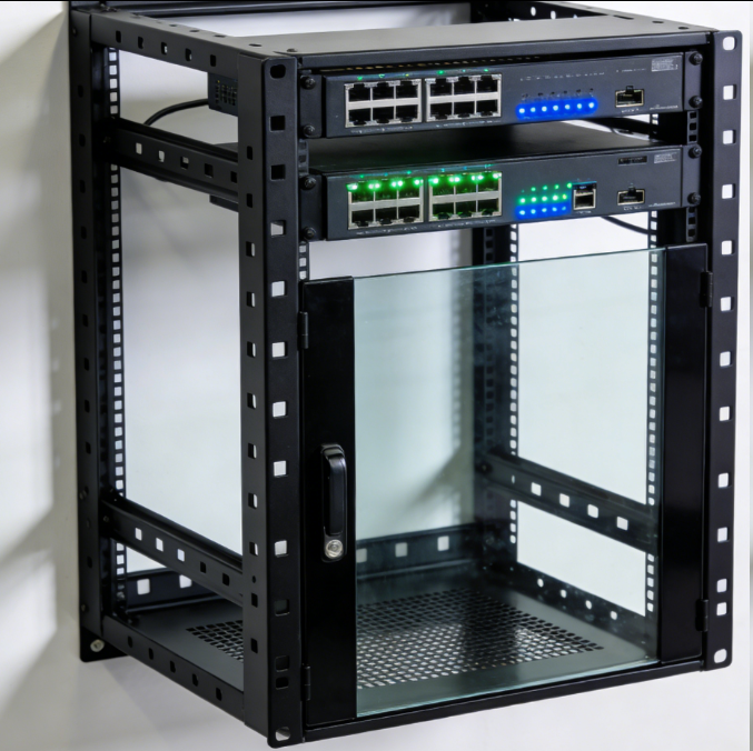
Network Rack Wall Mount 9U
Jan 06, 202677