- Language
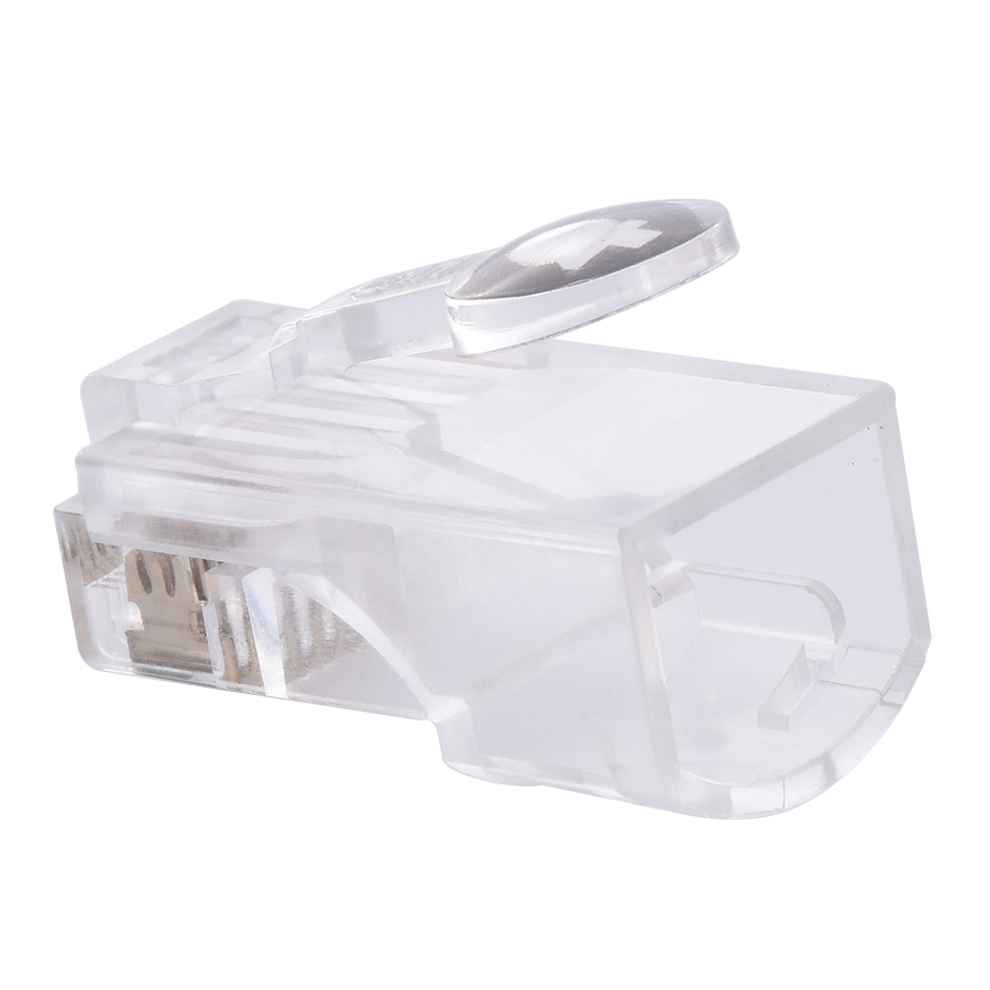
RJ45 Connector Wiring Scheme

The wiring scheme of an RJ45 connector is the foundation for establishing proper Ethernet connections, dictating how the individual wires within an Ethernet cable are connected to the pins of the RJ45 connector. There are two main wiring schemes in use: T568A and T568B, each with its own specific wire - to - pin arrangement, and understanding these schemes is crucial for network installation, maintenance, and troubleshooting.
The T568A wiring scheme arranges the wires in the following order from left to right (when the connector clip is facing down): white - green, green, white - orange, blue, white - blue, orange, white - brown, brown. This scheme was developed with the intention of providing better compatibility with older telephone wiring systems, as it aligns the green pair (which is often used for voice in some systems) with the first two pins. T568A is sometimes preferred in environments where there is a need to integrate Ethernet with existing telephone wiring or in situations where cross - over cables are frequently used. A cross - over cable, which is used to connect like - devices (e.g., two computers or two switches), is created by using T568A on one end of the cable and T568B on the other end. This reversal of the wire order swaps the transmit and receive pairs, enabling direct communication between the devices without the need for an intermediate hub or switch.
On the other hand, the T568B wiring scheme is more commonly used in modern Ethernet networks. In this scheme, the wire order is white - orange, orange, white - green, blue, white - blue, green, white - brown, brown. T568B has become the de - facto standard in many installations due to its simplicity and compatibility with a wide range of network equipment. Most pre - terminated Ethernet cables, network switches, and wall outlets follow the T568B standard. This standardization simplifies the installation process, as it allows for easy plug - and - play connectivity between different devices. For example, when connecting a computer to a network switch using a straight - through cable (where both ends of the cable use the same T568B wiring scheme), the data signals can be transmitted and received correctly without any additional configuration.
Regardless of the chosen wiring scheme, proper implementation is essential. Any misalignment of the wires in the RJ45 connector can lead to data transmission issues, such as slow speeds, dropped connections, or complete failure of the network link. Additionally, maintaining consistency in the wiring scheme throughout a network installation is crucial for ensuring seamless communication between devices. When troubleshooting network problems related to connectivity, technicians often start by checking the wiring scheme of the RJ45 connectors to rule out any incorrect wiring as the cause of the issue. In conclusion, the wiring scheme of RJ45 connectors is a fundamental aspect of Ethernet networking that directly impacts the performance and reliability of network connections.
Read recommendations:
Cat6 RJ45 8P8C Unshielded UTP Punch down Keystone Jack Module 90 Degrees Purple Jack 12pcs/Pack
LEG 77217 Socket Outlet Mosaic German Std 2P+E Auto term - 2 Mod - Orange Antimicrobial
-
-

-
-
-
-
-

-
-
-

Media Converter Network Patch Cord
Jun 27, 2026904
-

Network Cable Bandwidth Capacity
Jul 06, 2026895
-

UY2 Connector for Telephone Wire
Jul 08, 2026892
-

Wall-mounted Network Cabinet
Jun 30, 2026878
-

Four-Port Network Faceplate
Jul 03, 2026875