- Language
Insertion Loss of Network Cables
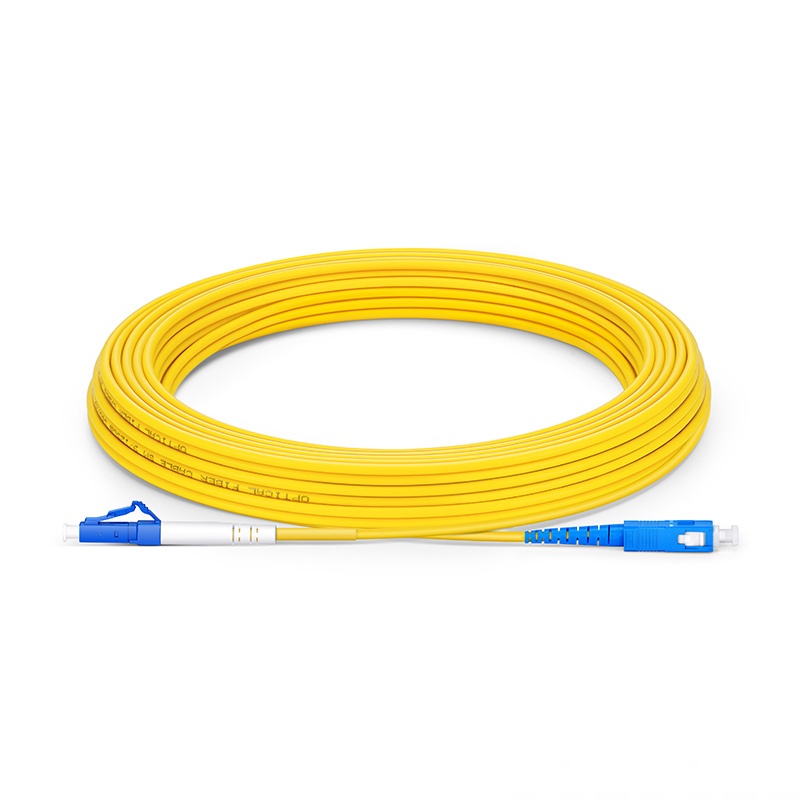
Network cable insertion loss is defined as the effective signal power loss generated when electrical or optical signals pass through network cable bodies, connectors, adapters and junction nodes, quantified by the decibel (dB) unit, representing signal attenuation degree in the entire transmission link. For copper twisted pair cables, insertion loss mainly comes from conductor resistance, dielectric absorption of insulating sheath and high-frequency signal dielectric heating; for optical fiber cables, insertion loss derives from fiber core impurity absorption, interface gap reflection and docking misalignment. Industry unified standards set maximum insertion loss thresholds for qualified cabling links: a standard 100-meter Cat6 copper link shall have insertion loss lower than 22dB at 250MHz working frequency, while a single LC-SC fiber adapter controls insertion loss below 0.2dB for qualified telecom use.
Multiple controllable and uncontrollable factors jointly determine the final insertion loss value of a complete network cabling link. Material quality is the fundamental factor: oxygen-free copper conductors reduce current resistance to lower copper cable insertion loss, while low-quality copper-clad aluminum cables produce 30% higher signal loss under the same laying length. Construction operation is the artificial key factor: excessive cable bending, over-tight bundle binding, stripped-over-long conductor ends and irregular crimping will sharply raise insertion loss. Environmental factors also play a vital role: long-term high temperature environment accelerates insulation material aging, changes dielectric constant, and increases high-frequency signal attenuation. In rainy and humid underground pipe laying scenarios, moisture intrusion inside cable jackets will cause localized signal leakage and rising insertion loss.
Controlling insertion loss within standard range is a core index for network acceptance and long-term stable operation. Excessive insertion loss leads to incomplete signal reception, frequent packet loss, network delay surge and automatic rate reduction of network terminals. For weak-signal remote monitoring links, ultra-high insertion loss will directly cause link disconnection and offline equipment. Professional cabling constructors test insertion loss via professional cable analyzers after wiring completion, replacing unqualified connectors and rearranging over-bent cables to optimize loss data. In large-scale data center design, engineers calculate cumulative insertion loss of the whole link in advance, including cable body loss, adapter loss, patch cord loss and distribution frame loss, to match optical transceiver transmit power and ensure full-speed network operation without signal attenuation failure.-
-
-
-
-
-
-
-
-
-
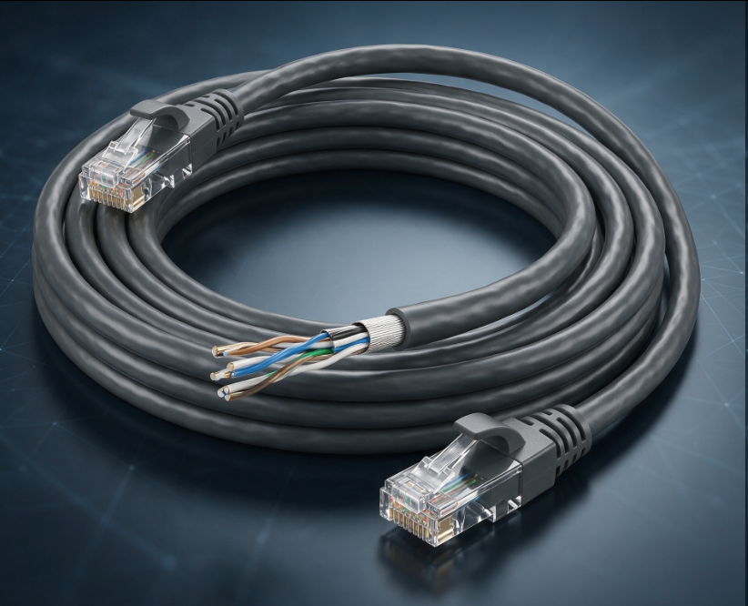
CAT6 Ethernet Gigabit Cable
Aug 15, 2026907
-

Media Converter Network Patch Cord
Jun 27, 2026906
-
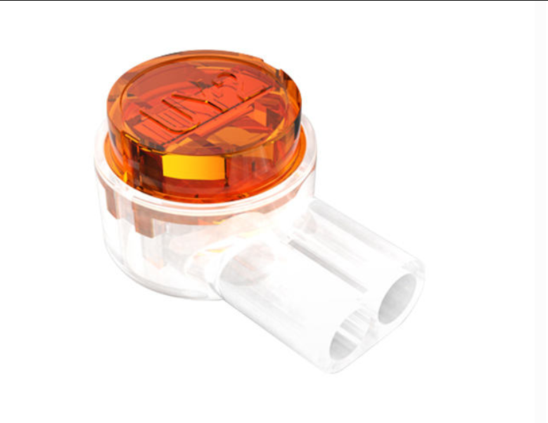
UY2 Connector for Telephone Wire
Jul 08, 2026897
-
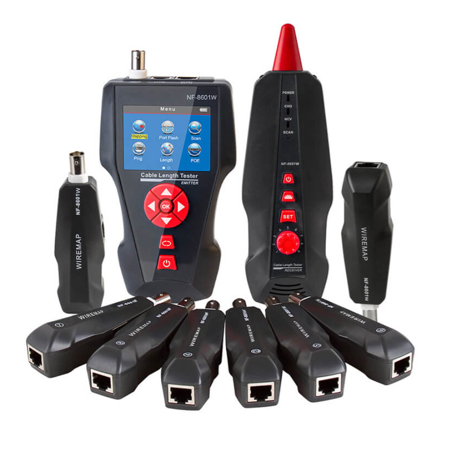
Network Cable Bandwidth Capacity
Jul 06, 2026897
-
Flame Retardant Cat7 Boot Cover
Jul 14, 2026888