- Language
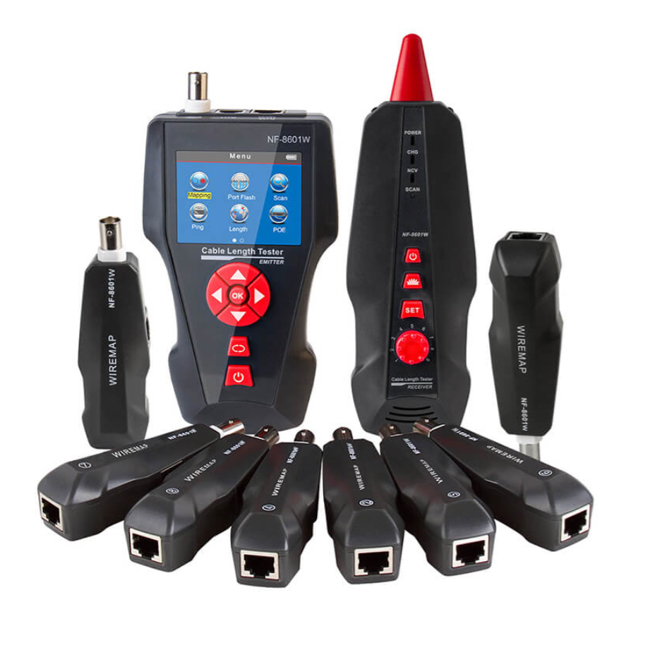
Network Tester LED Indicator

LED (Light - Emitting Diode) indicators on network testers serve as a visual interface that provides users with quick and essential information about the testing process and the status of network cables and connections. These small but powerful lights play a crucial role in making the tester's operation intuitive and user - friendly.
One of the primary functions of LED indicators is to show the basic connectivity status of the Ethernet cable being tested. When performing a continuity check, each LED typically corresponds to a specific wire or wire pair within the RJ45 connector. For example, if all the LEDs light up in sequence when the tester is running, it indicates that there is continuity for all the wires, meaning the cable is properly connected without any breaks. Conversely, if an LED remains unlit, it signals an open circuit in the corresponding wire, highlighting a potential problem that requires further investigation. This simple yet effective visual feedback allows technicians to quickly identify whether the cable is suitable for use in a network setup.
LED indicators also convey information about the type of fault detected in the cable. In addition to open circuits, they can indicate short circuits, where two or more wires are accidentally connected. When a short circuit occurs, the LEDs associated with the affected wires may display an abnormal pattern, such as lighting up simultaneously or in an unexpected sequence. By understanding these patterns, users can accurately diagnose the nature of the fault and take appropriate corrective actions, such as re - terminating the connector or replacing the cable.
For network testers that support advanced features, LED indicators are used to display additional information. In the case of cable length measurement, specific LEDs may blink or light up in a certain pattern to represent the measured length of the cable. Some testers use a combination of LEDs to show the progress of a more complex test, like network protocol analysis. As the tester examines the data packets and verifies protocol compliance, the LEDs may change their states to indicate different stages of the test, providing users with an understanding of how the testing process is progressing.
Moreover, LED indicators can also serve as power and status indicators for the tester itself. A dedicated power - on LED lights up when the tester is turned on, confirming that it is receiving power and ready for use. Other LEDs may indicate battery status in battery - operated testers. For example, a blinking red LED might signal a low - battery condition, prompting the user to recharge or replace the batteries to avoid interruptions during testing. Overall, the LED indicators on network testers are an essential component that simplifies the interpretation of test results, enables quick fault diagnosis, and provides valuable status information, enhancing the overall usability and effectiveness of the testing process.
Read recommendations:
LEG 77272 Multi-support Double Socket Mosaic - 2 x 2P+E Automatic Terminals German Standard Red
Network Rack 42U Mounting Rails
Cat6a Patch Cable 3m Technical Specifications and Performance Analysis
-
-
-
-
-
-
-

-
-
-

Media Converter Network Patch Cord
Jun 27, 2026904
-
Network Cable Bandwidth Capacity
Jul 06, 2026895
-
UY2 Connector for Telephone Wire
Jul 08, 2026892
-

Wall-mounted Network Cabinet
Jun 30, 2026878
-

Four-Port Network Faceplate
Jul 03, 2026875