- Language
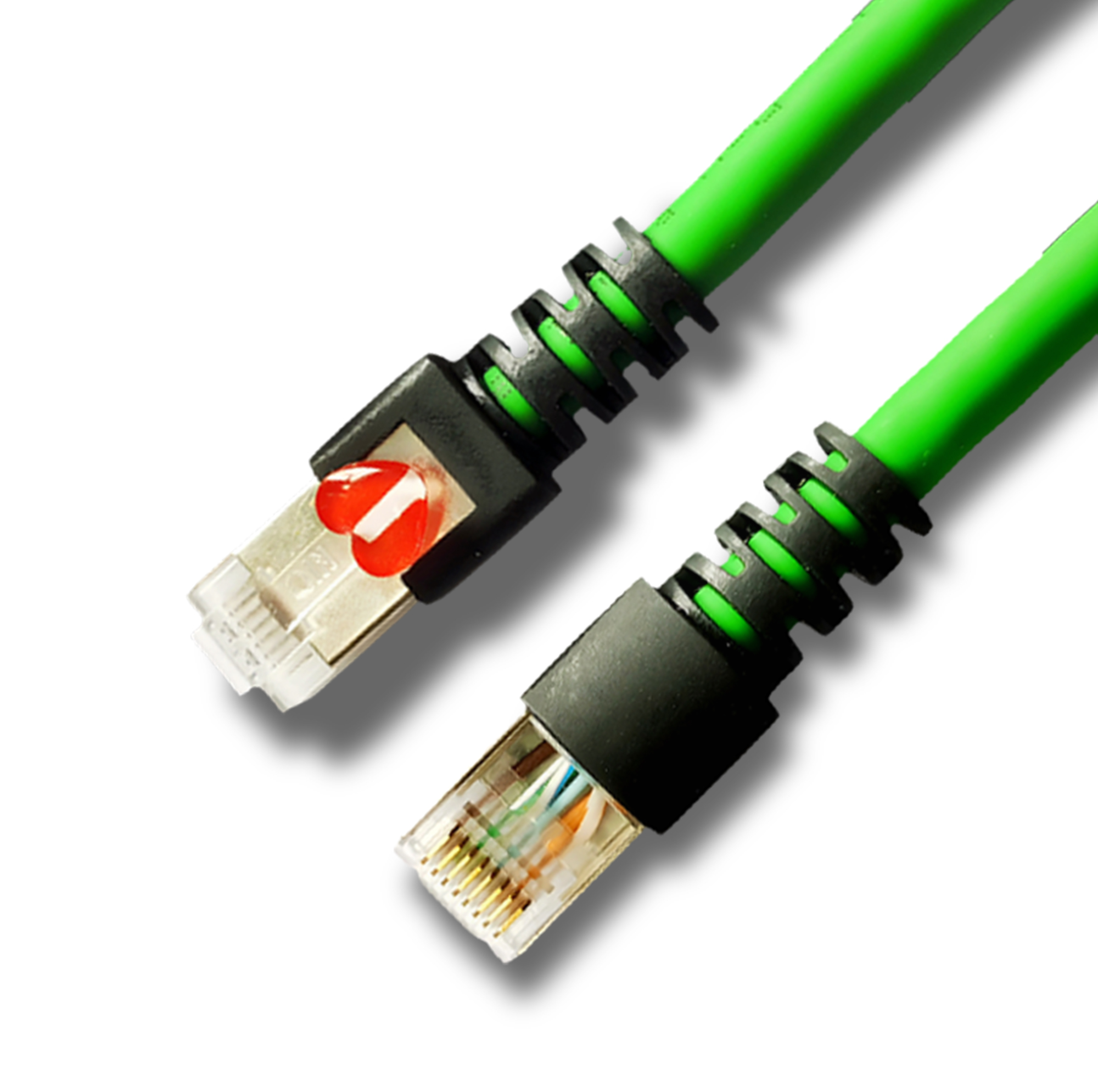
RJ45 Connector Pinout Diagram

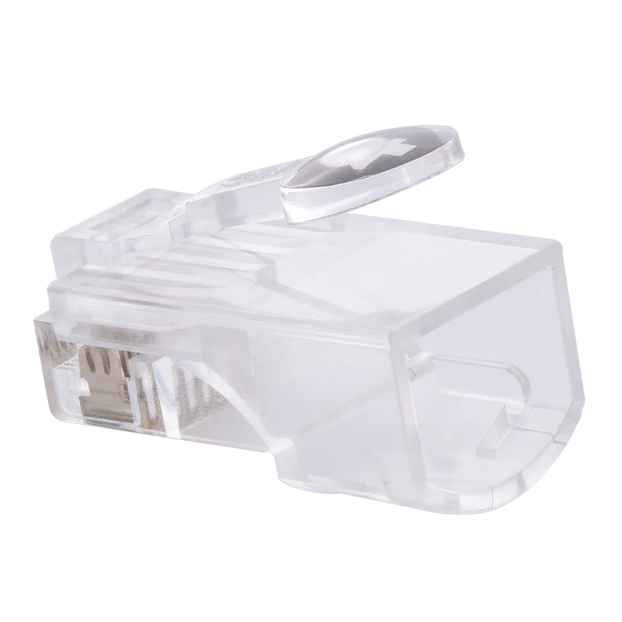
The RJ45 (Registered Jack 45) connector pinout diagram is a fundamental reference for understanding the electrical connections and signal transmission within Ethernet networking. This diagram illustrates the specific arrangement of pins inside the RJ45 connector, which is essential for proper cable termination, troubleshooting, and ensuring seamless data communication.
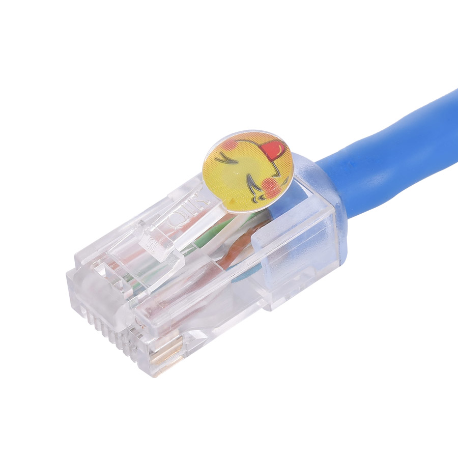
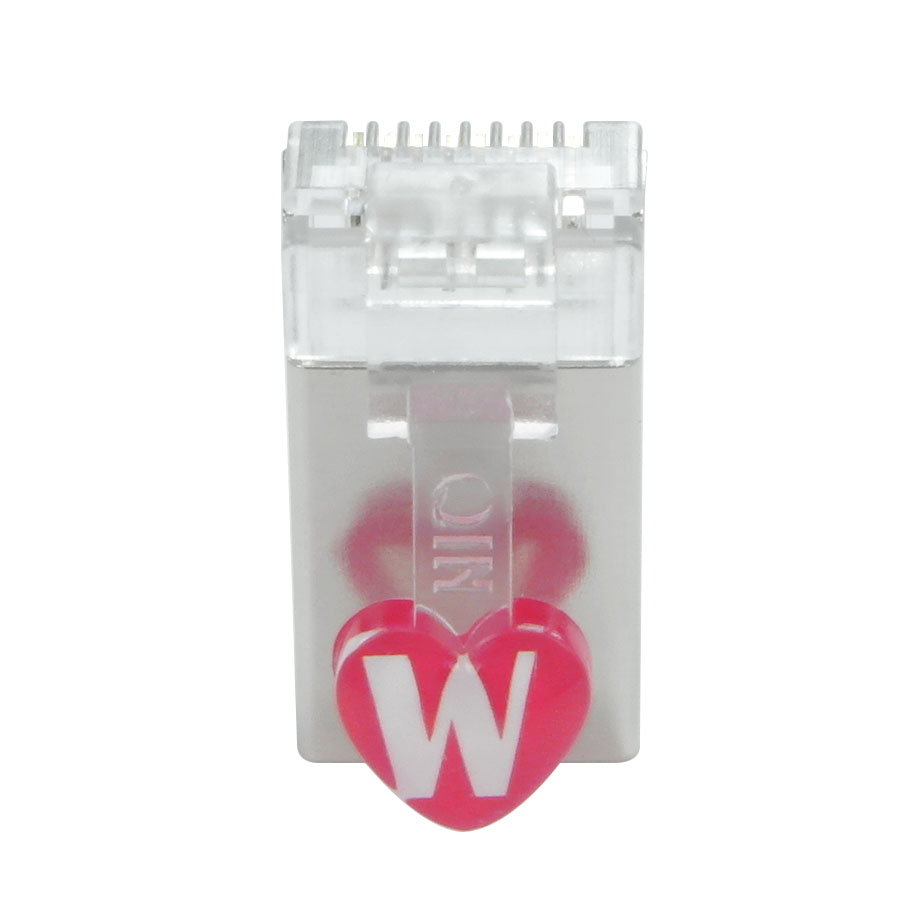
An RJ45 connector typically has eight pins arranged in a row. In the most common Ethernet applications, the pinout follows the T568B standard, which is widely adopted due to its compatibility and performance. According to the T568B standard, pin 1 is connected to the white - orange wire, pin 2 to the orange wire, pin 3 to the white - green wire, pin 4 to the blue wire, pin 5 to the white - blue wire, pin 6 to the green wire, pin 7 to the white - brown wire, and pin 8 to the brown wire. This specific wiring pattern is crucial as it determines how data signals are transmitted and received between network devices. For example, pins 1 and 2 are used for transmitting data, while pins 3 and 6 are used for receiving data. When two RJ45 - terminated cables are connected, the proper alignment of these pins ensures that data can flow accurately from one device to another.
Another pinout standard is T568A, which has a slightly different wire - to - pin mapping. In T568A, pin 1 is connected to the white - green wire, pin 2 to the green wire, pin 3 to the white - orange wire, and so on. Although T568A is less commonly used in general networking, it has its applications, especially in situations where cross - over cables are required. A cross - over cable uses a combination of T568A and T568B pinouts on each end of the cable. This allows devices of the same type, such as two computers or two switches, to communicate directly with each other without the need for an intermediate hub or switch. By reversing the transmit and receive pairs between the two ends of the cable using different pinout standards, data can be properly exchanged between the like - devices.
Understanding the RJ45 connector pinout diagram is also essential for cable assembly and repair. When terminating an Ethernet cable with an RJ45 connector, technicians must ensure that the wires are inserted into the correct pins according to the chosen standard. Any misalignment or incorrect wiring can lead to data transmission issues, such as slow speeds, dropped connections, or complete failure to communicate. Additionally, in network troubleshooting, knowledge of the pinout diagram helps technicians identify potential problems related to cable connections. For example, if a device is not receiving data, checking the pin connections against the diagram can help determine if there is a wiring error or a damaged pin within the connector. Overall, the RJ45 connector pinout diagram serves as a critical guide for anyone working with Ethernet networking, enabling proper cable installation, efficient communication, and effective problem - solving.
Read recommendations:
LEG 77252 Multi-support Double Socket Mosaic - 2 x 2P+E Automatic Terminals German Standard White
EU standard 16A 20A smart plug
Cat7 Modular Plug: Technical Specifications & Core Advantages
-
-

-
-
-
-
-

-

-
-

Media Converter Network Patch Cord
Jun 27, 2026904
-

Network Cable Bandwidth Capacity
Jul 06, 2026895
-

UY2 Connector for Telephone Wire
Jul 08, 2026892
-

Wall-mounted Network Cabinet
Jun 30, 2026878
-

Four-Port Network Faceplate
Jul 03, 2026875